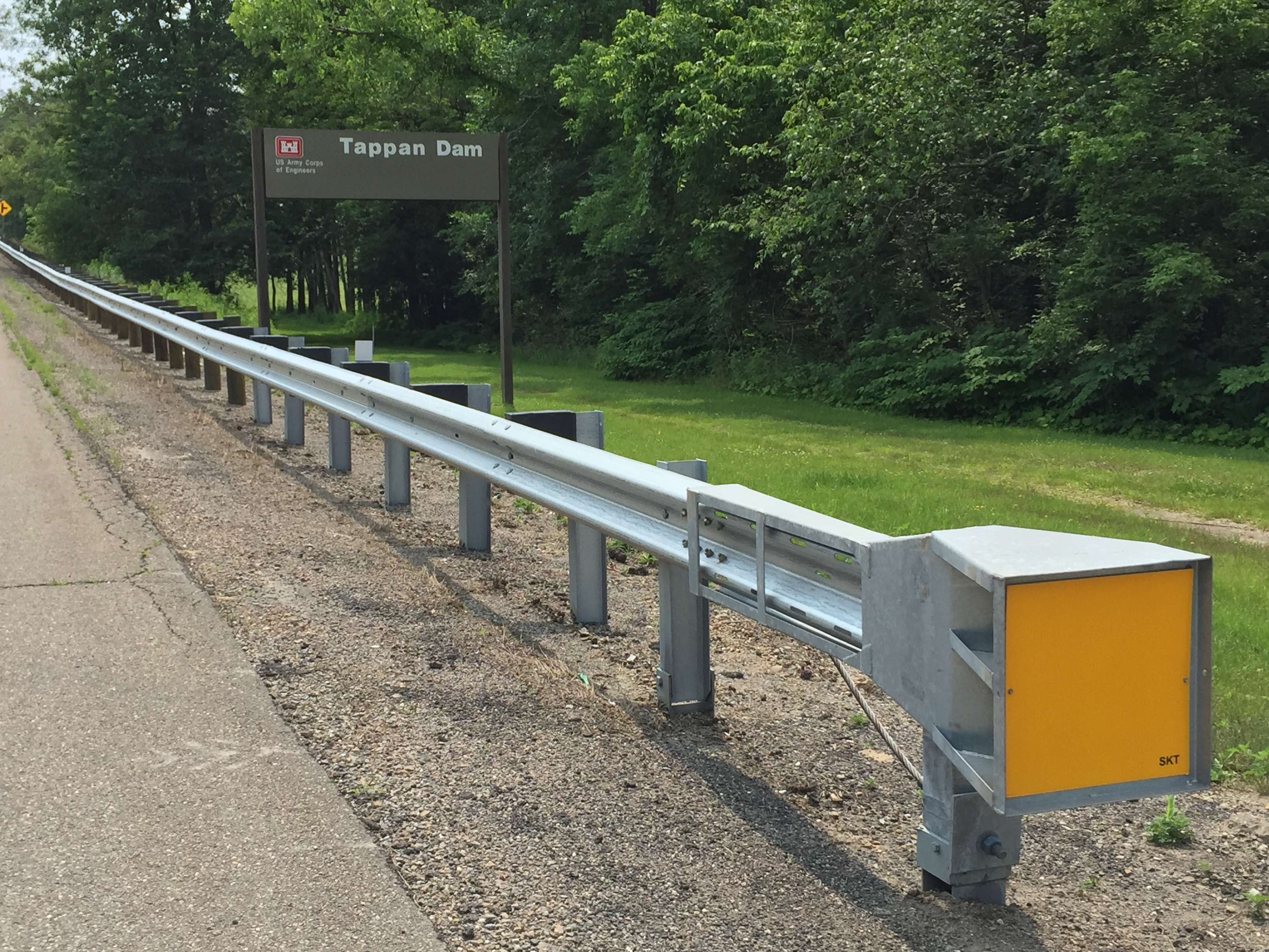
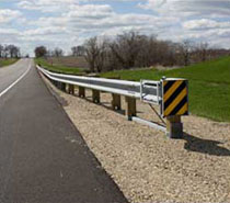
The SKT (tangent), FLEAT (flared), and FLEAT-MT (median) Terminals all have options for use with the MGS Midwest Guardrail System W-Beam Barrier.
Existing W-Beam barriers were developed many years ago when the vehicle fleet was different than it is today. These existing W-Beam barriers measure 27 3/4″ to the top of the rail. When crash tested with today’s higher center of gravity vehicles, many results have not been successful.
If you only raise the rail to 31″, that doesn’t mean it meets MGS requirements. Our terminals are actual MGS terminals; they have the special length rail section within the terminal to create the off-the-post splice and they have the option to use 12″ blocks within the terminal. That’s what’s required of an MGS Guardrail Terminal because the MGS requirements are not only the 31″ rail height.
The differences between the MGS Barrier and the older W-Beam barrier is:
- The MGS top of rail height is 31″ rather than 27 3/4″.
- The MGS blockout is 12″ rather than 8″. However, if the specifying agency has called for 8″ blocks on the downstream MGS W-Beam Barrier, 8″ blocks may be used in our terminals.
- The MGS W-Beam rail splices occur mid span between posts rather than at the post.
In 2001-2002, the Midwest States Pooled Fund Program funded by 11 States recognized the need for a new generic strong post W-Beam barrier that would be compatible with the newer higher center of gravity vehicles crash tested under NCHRP 350 Test Level 3 conditions. The result was the MGS Barrier.
Benefits & Features
- Terminals have the special length rail section within the terminal to create the off-the-post splice. There is no need to add another special rail section to the cost of the terminal or to the cost of the downstream W-Beam barrier.
- Terminals have the option to use 12″ or 8″ blocks within the terminal. There is no need to create a special transistion from a terminal with 8″ blocks to W-Beam barrier with 12″ blocks.
- Available in steel post or wood post options.
- Available with 12′-6″ or 25′-0″ rail sections.
- SKT-MGS and FLEAT-MGS available in Test Level 2 length at 25ft long.
- Most of the SKT-MGS, FLEAT-MGS, and FLEAT-MT-MGS components are interchangeable.